Sales of kits have reached the 360 mark!
The third batch of 50 Rev 1.5 boards have just arrived.
Unfortunatly the Polyvaricon used as the main tuning control has more than
doubled in price recently. I'm now on my 3rd supplier for these, unless
I can find a reliable and sensibly priced source the kit may have to be retired.
I will have to increase the kit price once existing stocks of the polyvaricon are used up.
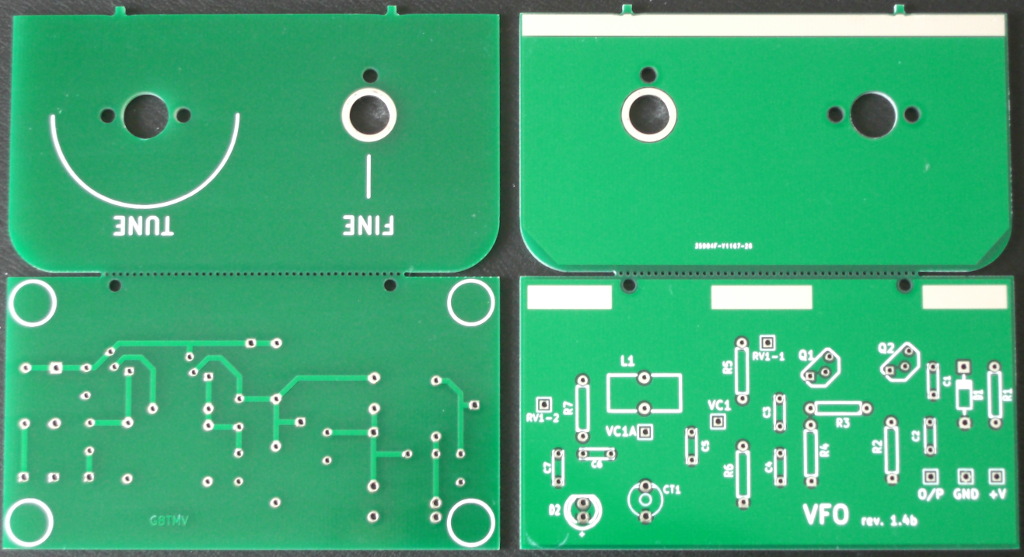
We are now up to Rev 1.5 boards, The layout has been updated to tidy things up a little. There have also been a couple of parts changes to try and make the calibration less twitchey. The trimmer is now 40pF and C5 has been increased to 120pF to compensate.
The new batch of rev 1.4b boards have arrived. The layout has been updated to move some of the parts away from the front panel to make assembly easier.
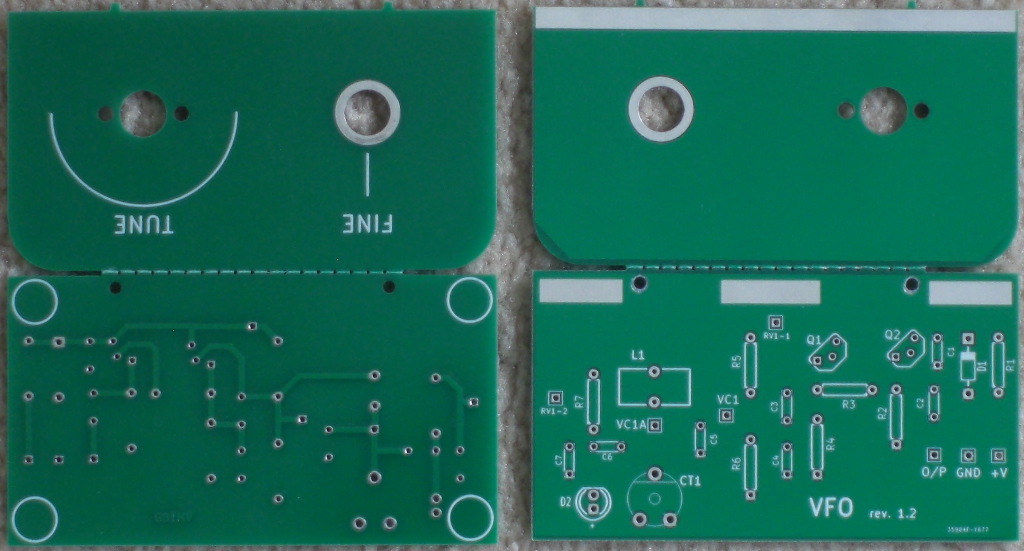
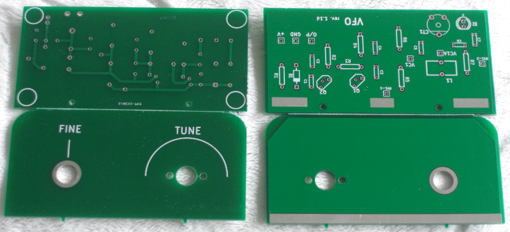
The new rev 1.4 boards have arrived. These use a ceramic trimmer rather than the previous film trimmer which was expensive and hard to obtain. The value has changed from 90pF to 65pF.
The new rev 1.3 boards have arrived. Unfortunately rising prices have meant that I've had to raise the kit price slightly.
The next batch of boards have been ordered from Hackvana.
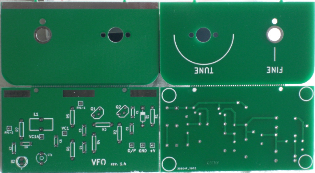
It's been apparent for some time that the frequency range/swing of the VFO did not quite cover all of the 80m band, typically it would be about 10kHz short. After some discussions it appeared that reducing the number of turns on L1 ought to solve the problem and I finally got around to trying it. Having reduced the number of turns to 58 (from 60) the swing of the prototype VFO does now cover all of the 80m band. We will do some more testing to decide on the best number of turns and then update the construction manuals.
Minor updates to the construction manuals to add capacitor markings. Also change parts list from 0.1uF to 100nF to match circuit diagram.
The rev 1.2 boards were delivered today.
Order placed for a new batch of boards (rev 1.2) and more parts to match.
The rev 1.1d boards have been (mostly) turned into kits and some of them have been sent out to customers. The manual has been updated. Work has started on the next cycle, the board is being made slightly narrower in an attempt to lower the cost slightly.
The rev 1.1d boards were delivered today, all the rest of the parts are already here so kitting can begin. The constructors manual will need updating too.
After a couple of minor hiccups a batch of the rev 1.1 boards is now in production.
The rev 1.1 version of the PCB is now ready.
Work has started on the next revision of the PCB. This will fix a few minor problems with the original design but the major change is altering the method of generating the tabs/slots that are used to assemble the boad so that we don't get charged a 'mill-out' fee.
The kiting is now complete since the missing resistors finally turned up.
A new draft of the construction manual is available, the kiting is now complete apart from a missing resistor in the fine-tune sub-kits.
The prorotype board is complete and working. The fine tune parts now also fitted. The fine tune control allows approx -4kHz/+3kHz of tuning.
The board with most of the parts fitted. The polyvaricon has to be fitted before the
toroid otherwise the ground connection is difficult to reach. 60 turns of 36swg wire
is not difficult to wind, it just takes patience.
Even without the polyvaricon wired the vfo should now run.
A frequency counter was connected to the output.
Power was applied and a signal was observed! Adjusting
the trimmer cap caused the output frequency to vary between approx 4MHz and 8MHz which was
about what was expected since there was much less capacitance present in the circuit
without the polyvaricon.
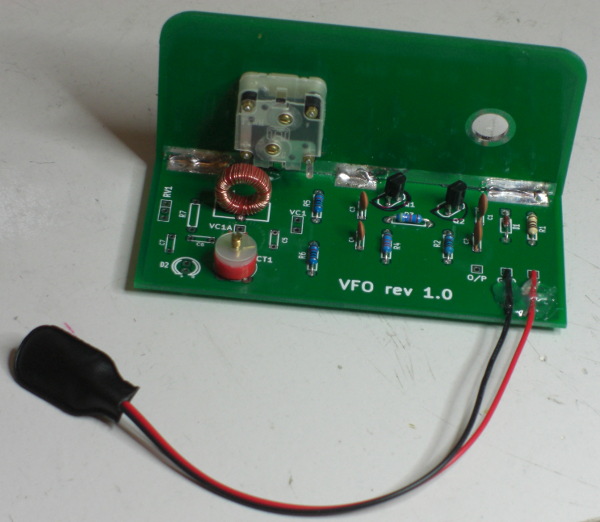
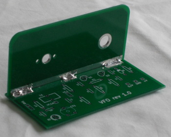
The board with the power supply parts fitted, note the hot glue used as strain relief on the battery leads.
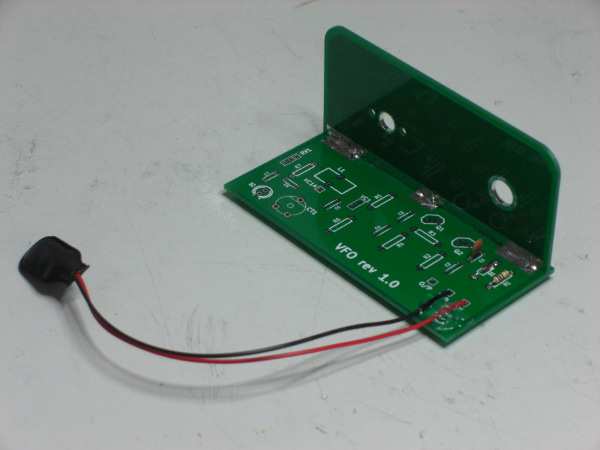
The board with the two halves soldered together.
The boards arrived. We ordered 10 initially and, as usual, Hackvana were kind enough to send us the overage from production so we have ended up with 11 boards. I now have 22 of the 26 parts on the BoM.
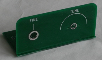
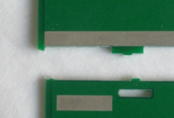
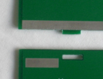
The first step is to seperate the two halves of the board. Using a pair of side cutters on the end webs and a craft knife to score the webs on the tabs makes it snap without damaging the tabs or slots. A fine flat file can then be used to remove the remains of the webs.
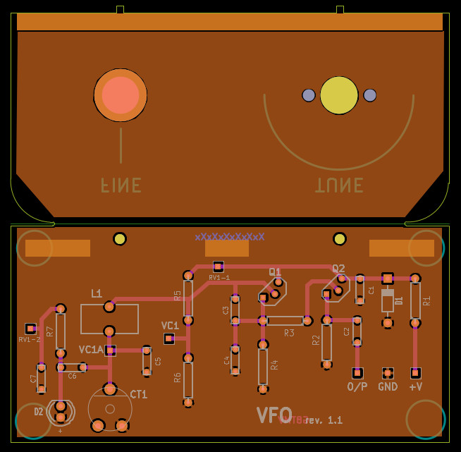
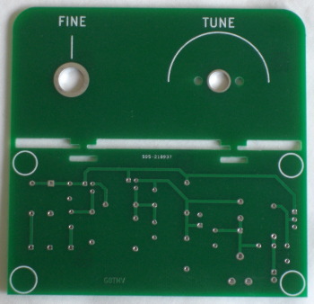
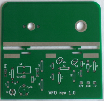
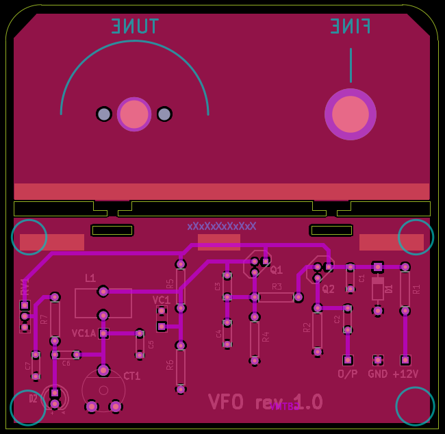
Here is an image of the pcb design which was produced using 'kicad'. The board is 10cm square and is designed to snap in half and then be joined at 90 degrees to form a circuit and a front panel.
![]()
![]()