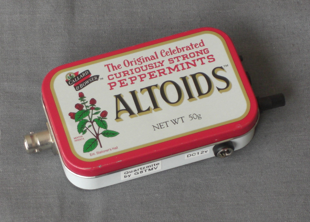
The radio installed in it's Altoids tin
The Quartzmite project started when I decided to build a surface mount version
of the popular 'Rockmite' QRPp CW transceiver. After talking with Dave Benson, K1SWL
the original designer and Chuck Carpenter, W5USJ who did some efficiency
modifications to the P.A. and low pass filter I came up with a variant of the
circuit that uses nearly all SMT parts.
Information on the first prototype can be found here.
As well as the improved Tx low pass filter my design makes use of the second op-amp
in the LM1458 to
implement a Sallen-Key second-order active low pass audio filter for the sidetone, making it
sound much less harsh than the square wave of the original Rockmite.
I've also put a pre-set pot in the sidetone circuit so the user can set the
sidetone volume independently of the Rx audio.
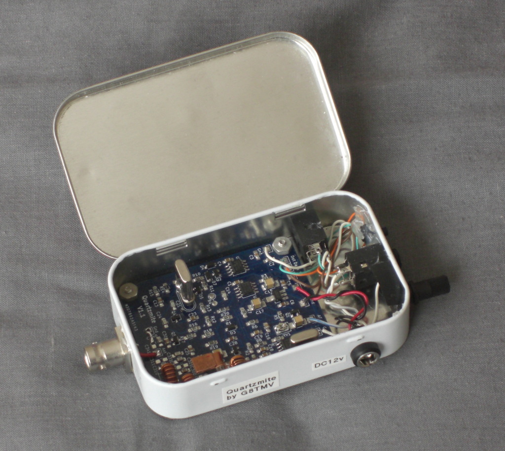
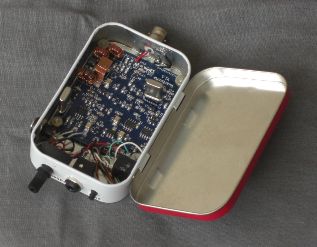
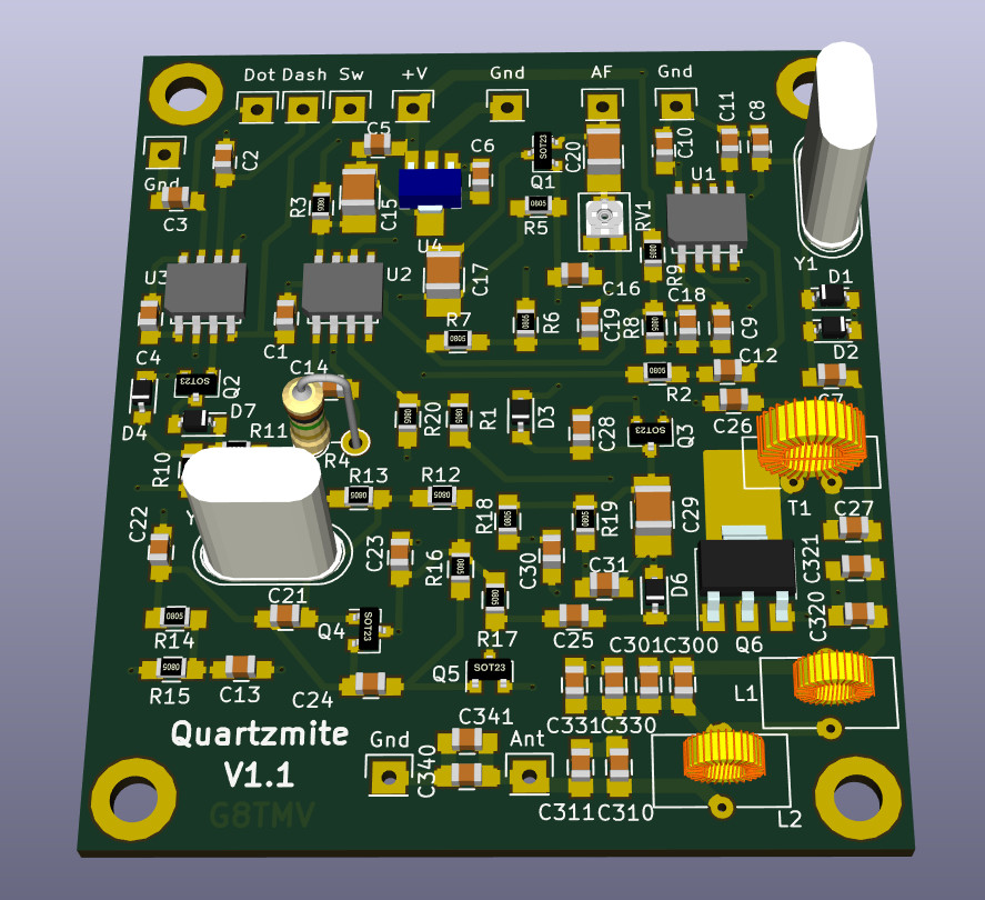
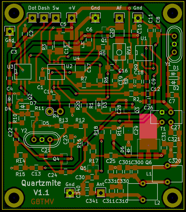
A printed circuit board was designed and sent out to be
made. There are some images below.
With a 12v supply it is delivering about 1 watt.
On Rx it draws about 15mA and on Tx about 370mA.
Some effort was focused on increasing the power output by adjusting things in the driver and PA
part of the circuit to make them more efficient.
One area that took some work was the 'shift' function that
moves the local oscillator between two frequencies about 700Hz apart,
this is used to separate the Rx
and Tx frequencies. The original Rockmite design is rather basic in this area and it has proved
impossible to get a sensible shift with any of the available zener diodes. After some experiments
I decided that rather than use a single zener diode to generate a reference voltage and use
ground (0v) for the other voltage, it was better to use two zeners with the lower voltage
one switched by the FET.
As well as making it easier to get the required shift this has the additional
benifit of allowing the use of the low end of the varicap capacitance range,
which means we are pulling the crystal less and so the oscillator is more stable.
The PCB is set up use HC49U wire ended crystals.
The output waveform on a 'scope is a nice sine wave and my spectrum analyser measured the
transmitter 2nd harmonic at -52dB so the low pass filter is performing as expected.
The last thing to do was to put it in an enclosure, I had an Altoids tin at the ready
since the board is designed to fit one with enough space left to mount the required sockets etc.
A PCB and board-level component kit was available, but are now all sold.
A schematic is available here,
a Bill of Materials here,
and a set of construction notes here.
The Quartzmite keyer is functionally identical to Dave Benson's original Rockmite keyer.
A quick push of the control button reverses the Tx/Rx frequency shift.
If a straight key with a mono plug is connected at power up then the iambic keyer is disabled
and the rig operates in straight key mode.
With paddles connected, pressing and holding the control button enters speed change mode where
one paddle increases the speed and the other reduces it.
![]()
![]()