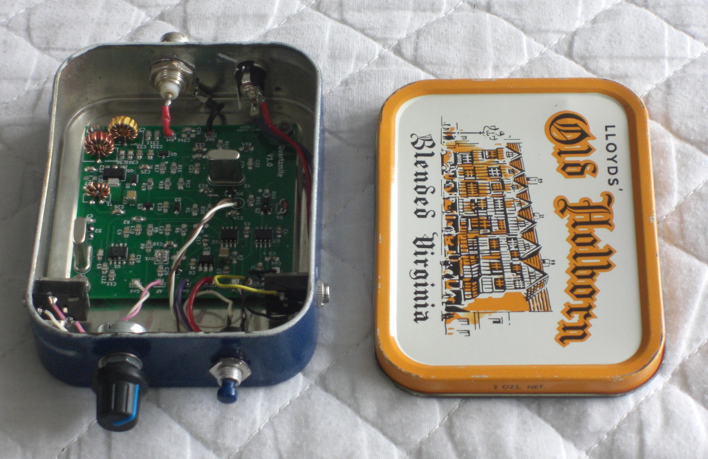
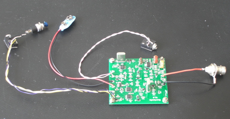
The prototype installed in it's tobacco tin.
The prototype was built and tested. With a 9v supply it
is delivering about 0.25 watts and with a 12v supply about 0.4 watts.
With the 12v supply on Rx it draws about 15mA and on Tx about 150mA.
Some effort was focused on increasing the power output by adjusting things in the driver and PA
part of the circuit to make them more efficient.
One area that took some work was the 'shift' function that
moves the local oscillator between two frequencies about 700Hz apart,
this is used to separate the Rx and Tx frequencies.
The original Rockmite design is rather basic in this area and it has proved impossible
to get a sensible shift with any of the available zener diodes. After some experiments
I decided that rather than use a single zener diode to generate a reference voltage and use
ground (0v) for the other voltage, it was better to use two zeners with the lower voltage
one switched by the FET.
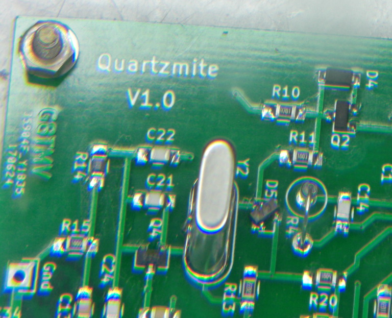
To do this on the prototype board I cut the track going to the drain of Q2
and inserted D7 between there and R10 where it just fits. As well as making it easier to
get the required shift this has the additional benifit of allowing the use of the low end
of the varicap capacitance range, which means we are pulling the crystal less and so the
oscillator is more stable.
The output waveform on a 'scope is a nice sine wave and my spectrum analyser measured the
transmitter 2nd harmonic at -52dB so the low pass filter is performing as expected.
The last thing to do was to put it in an enclosure, I had a 2oz tobacco tin at the ready
since the prototype board was (by design) slightly too big for an 'Altoids' tin.
A schematic is available here, a Bill of Materials here, and a set of construction notes here.
The Quartzmite keyer is functionally identical to Dave Benson's original Rockmite keyer.
A quick push of the control button reverses the Tx/Rx frequency shift.
If a straight key with a mono plug is connected at power up then the iambic keyer is disabled
and the rig operates in straight key mode.
With paddles connected, pressing and holding the control button enters speed change mode where
one paddle increases the speed and the other reduces it.
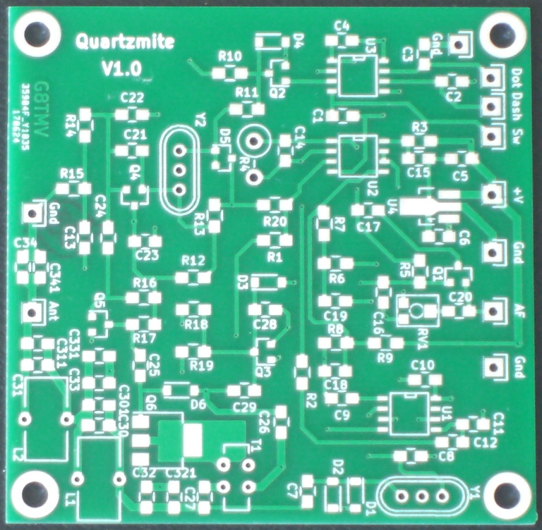
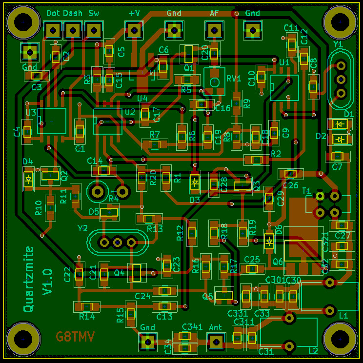
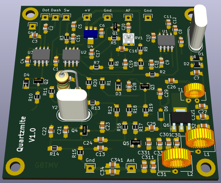
The version 1.0 pcb had a few bugs:
![]()
![]()