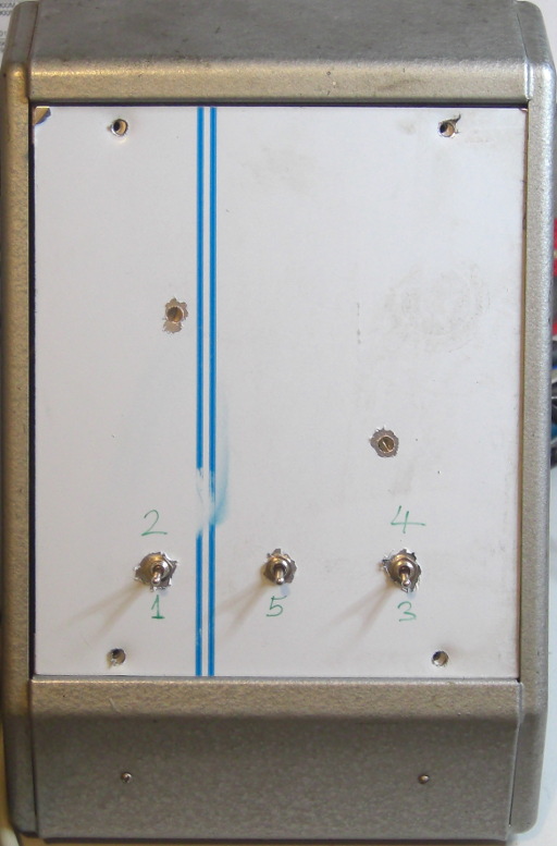
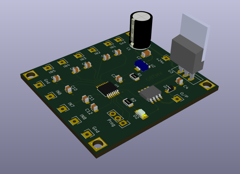
The prototype Master control unit.
The antenna remote control project started when I wanted to be able to do
more than just switch between my two EFHW antennas that share a feeder.
The antennas have quite a narrow bandwidth so I needed to be able to remotely
adjust the tuning of the feed matching by altering the capacitance in the circuit.
The system would also be suitable for controlling phased antenna arrays and some
experiments in this area are planned.
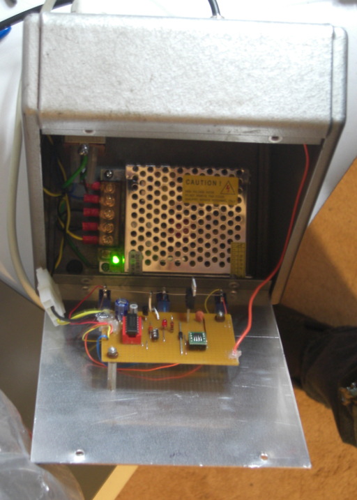
The project is still in the very early stages of development, photos of the prototype
are shown below. It should be noted that it was built almost entirely from parts in
my junk box and components stash, it's therefore vastly over engineered and much bigger
than required.
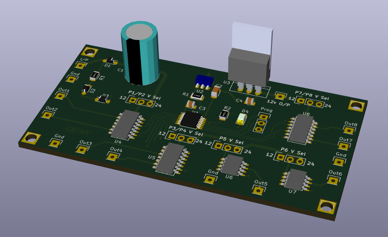
The unit reads the state of up to eight switches, converts the information into a serial
data stream and transmits it to the slave where it is recovered and used to drive up to eight
outputs, each controlled by a FET switch.
The system runs from 24 volts and the data stream is transmitted by switching the output line
from the master between 24v and 18v.
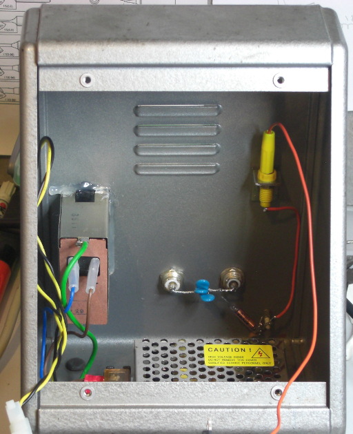
This method ensures that there is always power available at the slave end to
operate the slave controller and the relays or any other piece of equipment, for example, a
remote ATU.
The slave incorporates a 12 volt regulator so that either 12 volt of 24 volt
equipment can be supplied and controlled.
The output line is connected to the slave over the antenna coax via a pair
of "Bias-Tees".
On systems where Bias-Tees can be a problem, UHF systems for example, then a single core
wire (and the coax shield) is all that is required.
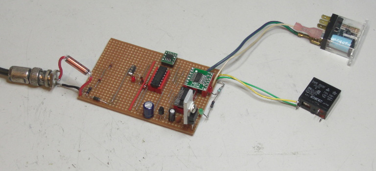
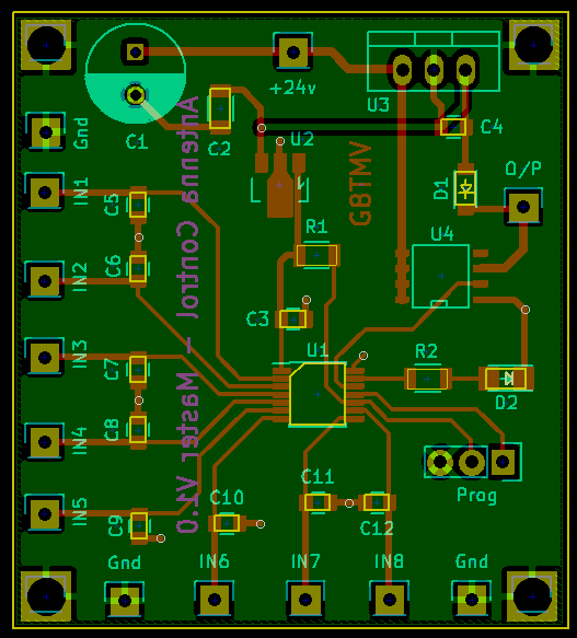
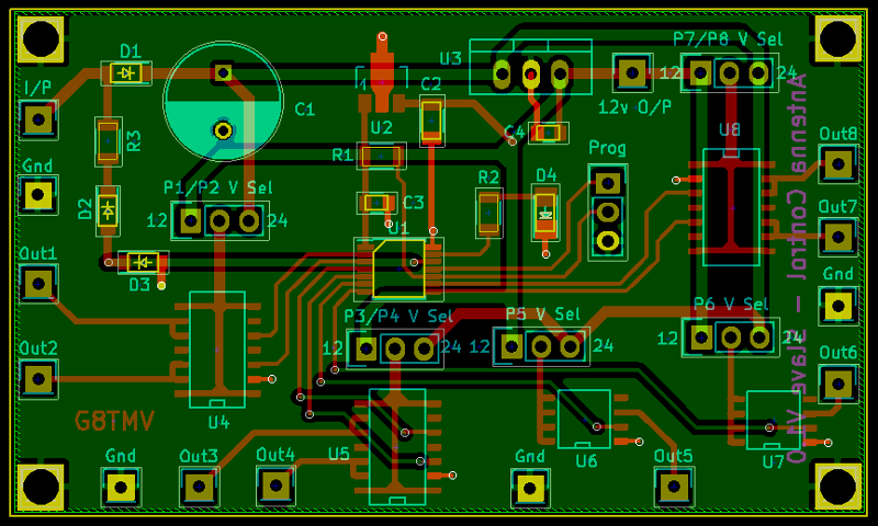
Now that the design is mostly stable printed circuit board design has started and there
are some images below.
![]()
![]()